Tests For Fire-Resistance Cables
09/06/2023
In the past, it has been observed that cables have caused spread of fire and the dissemination of toxic gases in many fire incidents. Therefore, the installation of fire-resistant cables and the use of these cables in fire safety systems have become crucial in crowded areas such as schools, hospitals, malls, cinemas, where fire safety measures need to be taken to prevent loss of life and property. Additionally, fire-resistant cables are used in systems that need to continue functioning during emergencies, just like in regular facilities.
Fire-resistant cables do not emit toxic gases during combustion, prevent the spread of flames, and have self-extinguishing properties due to their special components. In addition to low smoke density, fire-resistant cables have the ability to maintain circuit integrity for a certain period of time during a fire. Thus, fire-resistant cables provide additional time for the evacuation of the fire scene.
These cables, produced according to relevant standards, should be considered for their features such as low smoke emission, absence of halogen elements, flame retardancy and fire resistance to minimize the risk of loss of life and property and to ensure fire safety in buildings and facilities.
There are fire tests that simulate various fire scenarios to demonstrate that fire-resistant cables meet these expectations. These tests are divided into reaction-to-fire tests and resistance to fire tests.
Reaction to Fire Tests:
- Vertical Flame Test for Single Cable: IEC 60332-1-2
- Vertical Flame Test for Bunched Cables (IEC 60332-3)
- CPR Test (EN 50399)
- Smoke Denstiy Test (IEC 6134-2)
- pH and Conductivity Test (IEC 60754-2)
- Test for Determination of Halogen Acid (IEC 60754-1)
- Limiting Oxygen Index (ISO 4589-2)
Resistance to Fire Tests:
- Electric Transmission Continuity Test In Flame Environment (FE 180)
- Electric Transmission Continuity Test In Flame Environment (BS 6387 C)
- Electric Transmission Continuity Test Under Mechanical Impact (BS 6387 Z)
- Electric Transmission Continuity Test Under Water (BS 6387 W)
- Electric Transmission Continuity Test under Mechanical Impact (EN 50200)
- Electric Transmission Continuity Test under Mechanical Impact and Water (EN 50200 ANNEX E)
Reaction to Fire Tests
Vertical Flame Test for Single Cable: IEC 60332-1-2
The cable is fixed vertically from its ends to the test setup. The flame source is held at a 45° angle onto the cable. If the surface remains undamaged at the end of the test duration determined according to the cable diameter, the test is considered successful. The flame application time varies depending on the cable diameter, ranging from 60 to 480 seconds.
.jpg)
Vertical Flame Test for Bunched Cables (IEC 60332-3)
A steel ladder is fixed to the back of the test chamber, which is 1 meter wide, 2 meters deep, and 4 meters high. The base of the test chamber should have an airflow of 5000 liters per minute. The cable samples should have a length of 3.5 meters, and the number of samples and test duration should be determined according to the table below (based on category type). The test samples are attached to the ladder in a way that does not exceed a width of 300 mm. There should be a propane gas burner 600 mm above the floor of the chamber. After the test duration, the largest charred portion measured on the test sample should not exceed 2.5 meters from the point of ignition of the flame.


CPR Test (EN 50399)
CPR (Construction Products Regulation) is a regulation applied in the European Union for the placing on the market and free movement of construction products. CPR came into effect with European Parliament and Council Decision 2011/305/EU. The main purpose of CPR is to assess the performance of construction products in accordance with standards and provide users and notified bodies with accurate information through labeling. CPR covers various construction products, including fire-resistant cables. CPR requires the application of specific standards for the performance evaluation, classification, and marketing of fire-resistant cables. In this way, users and notified bodies can access to reliable information about the performance characteristics of the cables.
The EN50399 test apparatus is used to measure and to identify the behavior of cable under fire mounted on a vertical ladder. The number of test specimens is determined by measuring the outer diameter of the sample, and the samples are attached to the test ladder. During the test, measurements are taken for the amount of heat that released, smoke production, oxygen consumption, and CO2 production. This test allows for recording data from the moment the cable ignites, determining the progress of the flame on the cable through heat release measurements, and assessing the impact of smoke on visibility in the fire area through smoke production measurements.
The chamber is equipped with a system that blows air into the chamber at a rate of 8000 ± 400 Liters per minute. The test duration is 25 minutes, with a flame application time of 20 minutes.

Smoke Denstiy Test (IEC 6134-2)
Smoke emitted during fires situations reduces visibility and poses a risk of toxic gas poisoning, thereby decreasing the chances of escape or survival. For this reason, a smoke density test is conducts to determine the amount of smoke that a cable may emit in the event of a fire.
Smoke density is determined using a photoelectric cell that measures the intensity of light. The test is concluded if there is no drop in light transmission for 5 minutes after the fire source is extinguished or if the test duration exceeds 40 minutes. The light transmission should not be below 60%.

pH and Conductivity Test (IEC 60754-2)
For pH and conductivity measurement, approximately 1 gram of the sample is burned at 935°C in the testing machine. The resulting gases are absorbed into pure water. After the combustion process, the solution is transferred to a beaker from the rinsing bottles, and the solution is made up to 1 liter with distillate water and pH and conductivity are measured. The pH should be greater than 4.3, and the conductivity should be no more than 100 μS/cm.
Test for Determination of Halogen Acid (IEC 60754-1)
To determine the amount of halogen that contains in the cable, approximately 0.75 grams of the sample is burned in a silica glass at 800°C. The resulting gases are absorbed in a sodium hydroxide solution. After the combustion process, the solution of sodium hydroxide and generated gases is transferred to a separate container for titration. According to the standart, the halogen content should be less than 5 mg per gram for the test to be positive.

Limiting Oxygen Index (ISO 4589-2)
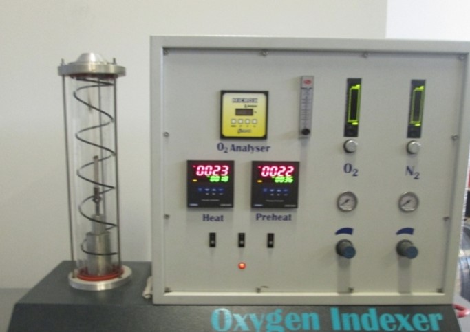
The Limiting Oxygen Index (LOI) test method is used to determine the minimum oxygen concentration required for the continued combustion of plastic materials under standart conditions. As specified in the ISO 4589-2 standard, a test specimen measuring 70-150mm in length, 6.5mm in width, and 3mm in thickness is securely clamped in the device. The required concentrations of oxygen and nitrogen gases are set, and the specimen is ignited using a propane flame with 2mm long, within the test chamber. With this test, the burning behavior of the specimen is observed. For a material with a known oxygen index, 15 ± 2 test specimens are sufficient, while for materials with unknown oxygen index, 15 to 30 test specimens are required. The specimen should extinguish within 180 seconds of ignition and the flame spread distance should not exceed 50mm. The highest oxygen concentration value at which the specimens meet these criteria is the oxygen index of the material.
Resistance to Fire Tests:
Electric Transmission Continuity Test In Flame Environment (FE 180)
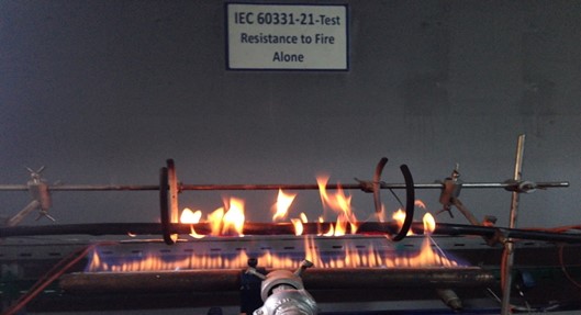
This test, which is applied according to the IEC 60331-21/23 standard, is commonly known as the FE 180 in the cable industry, where the circuit integrity is maintained for 180 minutes under the exposure to flame. The standard specifies the test conditions for a horizontally positioned cable, with a minimum temperature of 750°C -0/+50°C, where the flame source is placed 70mm above and 45mm away from the cable. The test is conducted for a duration of 90 minutes, ensuring that the circuit integrity remains intact without any disruptions.
Electric Transmission Continuity Test In Flame Environment (BS 6387 C)
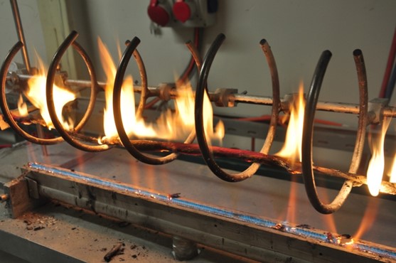
According to BS 6387 C standard, in this test, the cable is mounted on the test apparatus and the test is conducted. The declared voltage of the cable is applied to the conductors, and it is subjected to a flame at a temperature of 950 ± 40°C for 180 minutes. The cable tested for 180 minutes must maintain its electrical continuity.
Electric Transmission Continuity Test Under Mechanical Impact (BS 6387 Z)
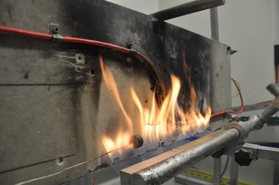
The cable is mounted on the wall in a Z-shaped configuration with a minimum bending radius and subjected to a flame at a temperature of 950 ± 40°C. The declared voltage of the cable is applied to the conductors, and every 30 seconds, a force produced by the free-falling action of a steel bar with a mass of 25 kg is applied to the wall where the cable is connected, striking it at a 60° angle. The cable tested for 15 minutes must maintain its electrical continuity.
Electric Transmission Continuity Test Under Water (BS 6387 W)
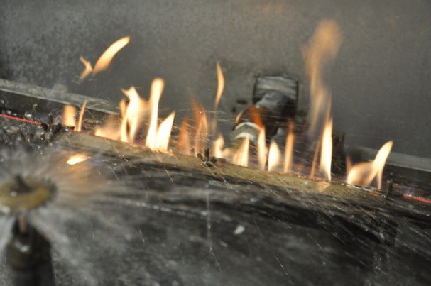
The test determines the electrical continuity is maintained when the cable is subjected to water spray under the declared voltage. The cable's declared voltage is applied to the conductors, and it is exposed to a flame at a temperature of 650 ± 40°C for 15 minutes. After the 15th minute, water is sprayed onto the cable in addition. The cable must maintain its electrical continuity for a further 30 minutes under the water spray.
Electric Transmission Continuity Test under Mechanical Impact (EN 50200)
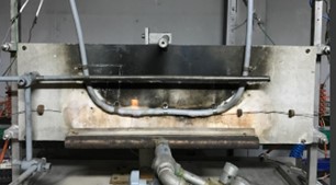
The cable is mounted on the test wall in a U-shape with a minimum bending radius, and it is exposed to a flame at a temperature of 830°C -0 +40°C. The cable's declared voltage is applied to the conductors, and every 5 minutes, a force produced by the free-falling action of a steel bar with a mass of 25 kg is applied to the cable by striking the wall it is connected to at a 60° angle. The cable's resistance duration determines its classification: PH15 for 15 minutes, PH30 for 30 minutes, PH60 for 60 minutes, PH90 for 90 minutes, and PH120 for 120 minutes. The cable must maintain its electrical continuity for the specified PH duration.

Electric Transmission Continuity Test under Mechanical Impact and Water (EN 50200 ANNEX E)
The cable is mounted on the test wall in a U-shape with a minimum bending radius, and it is exposed to a flame at a temperature of 830°C -0 +40°C. The cable's declared voltage is applied to the conductors, and every 5 minutes, a a force produced by the free-falling action of a steel bar with a mass of 25 kg is applied to the cable by striking the wall it is connected to at a 60° angle. It is then subjected to the flame at a temperature of 830°C -0 +40°C for a total of 15 minutes. After the 15th minute, water is sprayed onto the cable. The cable must maintain its electrical continuity for 30 minutes while under the water spray.
Written By: Mustafa Bilge - Halil Can Uğraşkan
